This process involves mapping a texture to a 3D object. The letters “U” and “V” denote the axes of the 2D texture, because “X”, “Y” and “Z” are already used to denote the axis from the 3D object in the model space.
UV texturing allows the polygons that make up the 3D object to be painted with a color from the image. The image is called a UV texture map, but it’s just an ordinary image. The process of UV mapping involves the assignment of pixels in the image of the surface mapping to the polygon, usually performed “programmatically” copying the shape of the triangle piece of the image map and paste it into the triangle on the object. UV is an alternative to XY, it just maps to texture rather than space to object geometry space. But the rendering calculation uses the UV coordinates of the textures to figure out how to paint the 3D surface
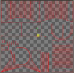
When the model is created as a polygon mesh using the 3D modeler, UV coordinates can be generated for each vertex. One way is for 3D modeling to develop them into a triangular mesh at the seams automatically.
A UV map can either be generated automatically in a software application, produced manually by an artist, or a combination of both. Often a UV map will be generated and then the artist will adjust and optimize it. If the model is symmetrical, the artist can overlap opposite triangles so that the painting is on both sides at the same time.
UV coordinates are applied to the face, not on top. This means that a common vertex can have different UV coordinates in each of its triangles, so that neighboring triangles can be cut apart and placed in different places in the texture map.
