Physical rendering (PBR) is an exciting, if loosely defined, real-time rendering trend of late. The term is quite fancy, often causing confusion as to exactly what it means. The short answer is: “many things” and “it depends”, which is rather unsatisfying, so I took it upon myself to explain what PBR is and how it differs from older rendering methods. This document is intended for non-engineers (artists most likely) and does not represent any math or code. Much of what makes the physical shading system different from its predecessors is the more detailed consideration of the behavior of light and surfaces. Shading capabilities have advanced so far that some of the old approximations can now be safely discarded, and with them some of the old means of art production. This means that both the engineer and the artist should understand the motivation behind these changes.
We’ll need to start with some basics well laid out before we start highlighting what’s new, but if you’ll bear with me through the parts you may already know, I think you’ll find it a good read. Then you may also want to check out Joe Wilson’s own article on creating PBR artwork.
Diffusion and reflection – also known as “diffuse” and “specular” light – are two terms describing the most basic separation of surface / light interactions. Most people will be familiar with these ideas on a practical level, but may not know how physically different they are. When light hits a surface boundary, some of it reflects—that is, it bounces off the surface and is directed toward the opposite side of the surface normal. This behavior is very similar to a ball thrown on the ground or against a wall – it bounces in the opposite direction. On a smooth surface, this will result in a mirror-like appearance. The word “specular”, often used to describe the effect, comes from the Latin for “mirror” (“specularity” seems to sound less unpleasant than “mirroring”).
However, not all light is reflected from the surface. Usually someone penetrates the interior of a lighted object. There it will either be absorbed by the material (usually by converting to heat) or diffused internally. Some of this scattered light can bounce back from the surface and again be visible to eyeballs and cameras. This is known by many names: “Diffuse Light”, “Diffusion”, “Subsurface Scattering” – they all describe the same effect.
In some cases, diffusion is more complicated—for example, with materials that have wider scattering distances, such as leather or wax. In such cases, simple color is usually not the case, and the shading system must take into account the shape and thickness of the object being illuminated. If thin enough, objects often see light scattering from the back and can then be called translucent. If the diffusion is even lower (in glass, for example), almost no scattering is seen at all, and the entire image can pass through the object from one side to the other intact. This behavior is so different from typical “near-surface” diffusion that unique shaders are usually needed for simulation.
With these descriptions, we now have enough information to reach the important conclusion that reflection and propagation are mutually exclusive. This is because in order for light to be scattered, the light must first penetrate the surface (that is, not be reflected). This is known in the shaded text as an example of “energy conservation”, which just means that the light leaving the surface is never brighter than what originally fell on it.
This can be easily enforced in a shading system: it simply subtracts the reflected light before you allow diffuse shading to occur. This means that highly reflective objects will show little or no scattered light, simply because little or no light penetrates the surface, which is mostly reflected. The converse is also true: if an object has clear diffusion, it cannot be particularly reflective.
Energy conservation of this kind is an important aspect of physical shading. It allows the artist to work with the reflectance and albedo values for the material without accidentally breaking the laws of physics (which tends to look bad). While enforcing these constraints in code isn’t absolutely necessary to create a good look, it serves a useful role as a “physical babysitter” to prevent artwork from bending the rules too much or becoming inconsistent in different lighting conditions.
Electrically conductive materials, especially metals, deserve special mention at this point for several reasons.
First, they tend to be much more reflective than insulators (non-conductors). Conductors typically exhibit reflectivity of up to 60-90%, while insulators are generally much lower, in the 0-20% range. These high reflectivities prevent most of the light from entering the interior and scattering, giving metals a very “shiny” appearance.
Second, the reflectance on conductors sometimes varies across the visible spectrum, meaning their reflections are colored. This coloration of reflection is rare even among conductors, but occurs in some everyday materials (e.g. gold, copper and brass). Insulators generally do not show this effect and their reflections are uncolored.
Finally, electrical conductors usually absorb rather than scatter any light that penetrates the surface. This means that in theory the conductors will show no evidence of diffuse light. In practice, however, there are often oxides or other residues on the metal surface that scatter a small amount of light. It’s the duality between metals and just about everything else that causes some rendering systems to accept “straightness” as a direct input. In such systems, artists specify the degree to which a material behaves like a metal, rather than specifying only albedo and reflectance explicitly. This is sometimes preferred as a simpler means of creating materials, but is not necessarily a characteristic of physical rendering.
In computer graphics, the word Fresnel refers to the different reflectivity that occurs at different angles. Specifically, light that hits a surface at a grazing angle will be much more likely to reflect light that hits the surface. This means that objects rendered with the correct Fresnel effect will appear as brighter reflections near the edges. Most of us have known it for a while, and its presence in computer graphics is not new. However, PBR shaders made popular several important corrections in the evaluation of the Fresnel equations.
The first is that for all materials, the reflectivity becomes the total angle for matching – the “edges” seen on any smooth object should appear as perfect (untinted) mirrors regardless of the material. A second observation of Fresnel properties is that the curve or gradient between angles does not vary significantly from material to material. Metals are the most divergent but can be analyzed analytically. For us, this means that, assuming realism is desired, the artificial control of Fresnel behavior should generally be shortened rather than extended. Or at least now we know where to set the default values!
This is good news because it can simplify content creation. The shading system can now handle the Fresnel effect almost entirely independently; it only has to consult some of the material’s pre-existing properties, such as gloss and reflectivity.
The PBR workflow has the artist determine the “base reflectance” in one way or another. This provides the minimum amount and color of reflected light. The Fresnel effect, once rendered, will add reflectivity above the artistic value, which goes up to 100% (white) in the viewing angle. Basically, the content describes the base and the Fresnel equations take over from there, making the surface more reflective at different angles as needed.
However, there is one big piece that is still missing. Most real surfaces have very small imperfections: tiny grooves, cracks and lumps too small for the eye to see and too small to show up in a normal map of any reasonable resolution. Although invisible to the naked eye, these microscopic features affect the diffusion and reflection of light.
Microscopy detail has the most obvious effect on reflection (subsurface diffusion is not significantly affected and will not be discussed further here). In the diagram above, you can see that the parallel lines of incoming light begin to diverge as they bounce off a rougher surface, as each ray hits part of the surface in a different orientation. The analog in the ball/wall analogy would be a section of rock or something like that unevenly: the ball still bounces, but at an unpredictable angle. In short, the rougher the surface gets, the more the reflected light will vary or appear “blurry”.
Since our hypothetical shading system now takes microscopic details into account and diffuses the reflected light appropriately, it must carefully reflect the correct amount of light. Unfortunately, many older renderings got this wrong, reflecting too much or too little light, depending on the roughness of the surface.
When the equations are properly balanced, the renderer should display rough surfaces with larger reflective highlights that appear more muted than smaller, sharper smooth surface areas. It’s the apparent difference in brightness that’s key: both materials reflect the same amount of light, but the rougher surface spreads it out in different directions, while the smoother surface reflects a more concentrated “beam”:
And it is with the above-mentioned knowledge that we come to the realization, a great fact: the microscopic gloss directly affects the apparent brightness of the reflection. This means the artist can draw variations directly into the glossy map—scratches, dents, sanded or polished surfaces, you name it—and the PBR system will display not only the change in the shape of the reflection, but also the relative intensity. No “spec mask” / reflectivity change required!
This is significant because two real-world quantities that are physically related—microscopic detail and reflectance—are now, for the first time, properly linked in the artistic content and rendering process. This is similar to the diffusion/reflection balancing act described earlier: we could create with both values independently, but since they are related, the task is only made more difficult by trying to treat them separately.
Furthermore, real-world material detection will prove that reflectance values do not change (see the previous section on conductivity). A good example would be water and mud: they both have very similar reflectivity, but because the mud is quite rough and the surface of the puddle is very smooth, they appear to be very different in terms of their reflections. An artist creating such a scene in a PBR system would distinguish primarily through maps.
BRDF
- Albedo
- Specular
- Roughness
- Normal
Albedo is the characteristic color of an object. More precisely, it is the bi-hemispheric surface reflectance. It is an independent view and is generally called diffuse.
Traditional artists used to “store” lighting information in diffuse structures such as ambient occlusion, shadow, and reflection. The lighting is now separated and must be removed from the albedo texture. The lighting in the game will all come from the graphics engine.
- Albedo value is between 32-243 in sRGB
- One of the darkest substances on earth is coal, the brightest is fresh snow
- Pure metallic objects have an albedo of 0
- White R=243 G=243 B=242
- Neutral 8 R=200 G=200 B=200
- Neutral 65 R=160 G=160 B=160
- Neutral 5 R=122 G=122 B=121
- Neutral 35 R=85 G=85 B=85
- Black R=52 G=52 B=52
The mirror structure is difficult for artists to understand because it is based on the concepts of physics. However, authorship is simple because there is no artistic interpretation for him. The specular structure controls the specular reflectivity of the surface. It is used as input to the Fresnel equation, which calculates how much light is reflected.
The specular reflectance of a surface depends on its index of refraction (IOR). In terms of specular reflectivity, surfaces commonly used in the game can be divided into three main groups:
- metal (conductor)
- non-metallic (insulators such as water, glass, skin, wood, hair, leather, plastic, stone, concrete)
- precious stones (semiconductor)
Gems are uncommon and will not be relevant to remember me. Metals are highly reflective for all incidents and tracking directions. Their specular reflectance is colored because their IORs tend to vary significantly with the wavelength of light. At the opposite end are non-metals, which are poor reflectors when looking straight down, but at an eel, they reflect most of the light. Their specular reflectance is monochromatic because their IOR does not vary with the wavelength of light and can be approximated by a constant.
To avoid artists struggling with IOR – which is difficult to understand (especially for metals with a complex index of refraction that varies with the wavelength of light), the team used specular reflectance at normal incidence F0 (0° incidence angle, direct view + light ) as the input of our Fresnel Schlick approximation.
F0 can be displayed as a color. Thus, F0 is the specular structure content (can be called specular colored) and can be obtained from IOR with the following equation: F0
The main chart guidelines (in linear RGB here) are:
- No value is less than 0.02
- The value of non-metals is intuitively low: 0.02-0.08
- Precious stones are 0.05-0.17
- Metals have a high specular reflectivity: 0.5-1.0
If the metal IOR is not known, a standard value of 0.04 (around plastics) was used. It can be observed that the F0 of the metal corresponds to the characteristic color of the metal under white light. It allows artists to easily set the F0 for a non-reference metal based on what they think the color is. Moreover, the metal has no subsurface interaction and therefore should have a black albedo.
In practice, artists have experienced that for all non-metals F0 could be left at 0.04 without any visual change. This is due to the limitation of the game’s graphics engine. A common mistake was not setting the black albedo to metal (it doesn’t seem clear to the artist that it should be black). Mostly mirror texture is a small structure with flat colors.
The implicit statement in the definition of F0 used here is that it corresponds to the specular reflectance of the material in contact with air (which it almost always is, but not always). This F0 value is not valid if, for example, underwater underwater. Memorize a lot of wet surfaces. (In this case, the value of 1, which is the IOR of air in the F0 equation – should be replaced by the value of 1.33 – the IOR of water).
For insulators, IOR values do not require color information and can be entered directly into the index field, while the extinction field should be set to 0. For metals that have color reflections, a value must be entered for the red, green, and blue channels. This can be done using a map input (where each channel of the map contains the correct value). An extinction value will also need to be set for the metals that you typically find in libraries that contain IOR values.
Texture roughness is one of the two most important textures that artists create – the other being a normal map. When the surface is perfectly smooth, the reflection is sharp (specular). When the surface is rough, the reflected light rays deviate from the mirror’s ideal direction and the reflections begin to blur. The distribution of deflected rays, which are important for reflection, can be represented by a cone around the ideal direction of the mirror. The roughness texture controls the cone aperture and thus the reflection blur. The rougher the surface, the larger the cone.
However, the content of the roughness structure depends on the specific convention of the graphics engine and on the normal distribution function used in BRDF (making it difficult to reuse for other graphics engines). For example, it rarely stores the opening angle of the cone.
The textual content of roughness as a numerical value is often difficult for artists to interpret. The roughness values are interpreted by the graphics engine as if it were the opening angle of the cone. For indirect lighting, it is used to select the mipmap in the cubemap. For direct lighting, it converts to specular power.
- 0 – black – means rough
- 255 – white – means smooth
In fact, Normal is the same as the traditional lighting model, so the artists were very happy with the control and of course they didn’t need a guide.
Roughness texture is related to normal texture in many ways. Both represent the geometric features of the surface, but at different scales. The normal scatter of the normal map will affect the texture of the roughness (a bumpy surface represented by a normal perturbation should be rough, for example). Other surface imperfections such as scratches, blemishes, pores, etc. are added to the roughness structure. In Remember Me, the roughness texture in the alpha channel is a normal texture map, which prompted the artists to create these texts together and at the same resolution.
Ambient
Ambient occlusion (AO) represents a large illuminated light and is generally baked from a 3D model.
Adding the AO as a separate map as opposed to baking into the albedo and specular map allows the shader to use it more intelligently. For example, the AO function only blocks diffused ambient light, not direct diffused light from dynamic lights or reflective reflections of any kind. AO should generally not be multiplied by mirror or glossy maps. Multiplying the AO on a specular map may have been a common technique in the past to reduce inappropriate reflections (e.g. the sky reflecting off a jagged object), but these days local space reflections on the screen are much better at representing inter-object reflections.
A cavity map represents a light flash of small size and is generally baked from a 3D model or a normal map. The void map should only contain the concave areas (pits) of the surface and not the convex areas, as the void map will be multiplied. The content should be mostly white with darker parts representing sunken areas of the surface where light could be caught. The cavity map affects both diffuse and specular from ambient and dynamic light sources.
trainz-build 4.6
username "PBR Cliffs - Seasonal"
kind "groundtexture"
category-class "gl"
description "PBR environment texture"

thumbnails
{
0
{
image "dlsthumbnail.jpg"
width 240
height 180
}
}
texture "albedo.texture"
normal-texture "normal.texture"

texture-variants
{
0
{
diffuse-texture "albedo.texture"
normal-texture "normal.texture"
parameters-texture "parameters.texture"
}

3
{
diffuse-texture "albedo_winter.texture"
normal-texture "normal.texture"
parameters-texture "parameters_winter.texture"
}
}

season-selector
{
above-snow-line 1

branch-true
{
output-season 3
}

branch-false
{
output-season 0
}
}

kuid-table
{
}
Primary=albedo.tga Alpha=albedo.tga Tile=st
Primary=parameters.tga
Alpha=parameters.tga
Tile=st
Primary=normal.tga
Alpha=normal.tga
Tile=st
NormalMapHint=normalmap
texture-variants
{
0
{
diffuse-texture "albedo.texture"
normal-texture "normal.texture"
parameters-texture "parameters.texture"
}

3
{
diffuse-texture "albedo_winter.texture"
normal-texture "normal.texture"
parameters-texture "parameters.texture"
}
}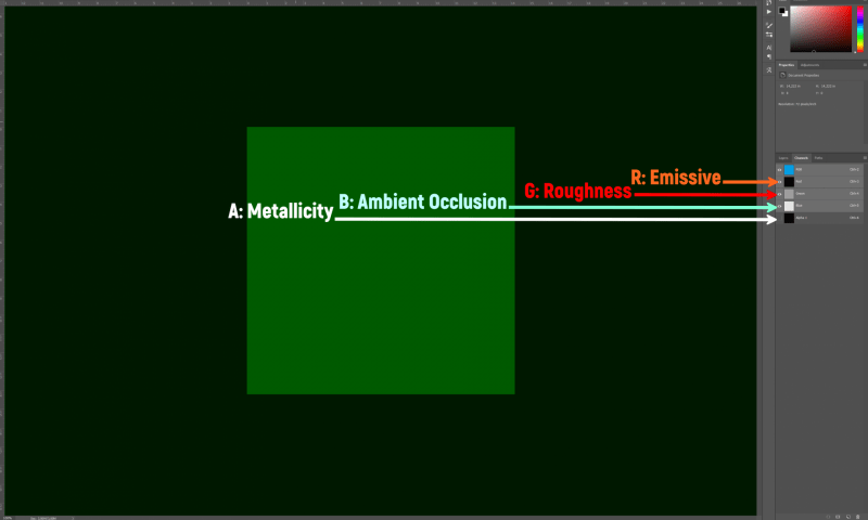
| Base Color | sRGB | Base Color |
| OcclusionRoughnessMetallic (Green channel) | Linear | Roughness |
| OcclusionRoughnessMetallic (Blue channel) | Linear | Metallic |
| OcclusionRoughnessMetallic (Red channel) | Linear | Ambient Occlusion |
| Normal Map | Normal | Normal |
