Normal mapping means a line drawn perpendicular to the surface in a plane, on the flat part of the surface the normal points straight up towards the vertex. TRS compares the direction of the normal with the direction of the current ambient light source and uses the result to calculate how much light is falling on the surface and how bright it should be lit. For an object that only has a rectilinear diffuse structure, the normal is always perpendicular to the surface of the object, and the way the object bends light rays will only be determined by the angle of the object relative to the light source.
Normal mapping allows this lighting calculation to be adjusted for each screen pixel used to render the object. An additional value, calculated from the red, green and blue components of the normal map, is included in the lighting calculation. This forces TRS to render each pixel of the object in a different way and can be used to create the impression of three-dimensional shapes that are not actually present in the actual model.
Trainz Simulator has been using this technology since TS 2009
The model can be exported with a plugin that N3V makes available for 3ds max up to version 2012. For the new versions 2013 and later, you need to proceed manually by directly exporting the FBX model and textures, but basically it remains. that the heightmap must contain the following statement in the material.
.m.tbumptex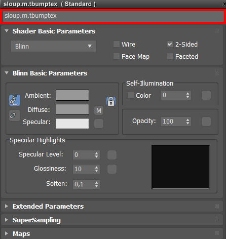
What exactly is Normal Map and mapping?
“Normal” is a line drawn perpendicular to the surface of the board, on a flat part of the ground the normal points vertically upwards towards the top. TRS compares the direction of the normal with the current direction of the surrounding light source and uses the result to calculate how much light is hitting the surface and how bright it should be.
For an object that only has a direct diffuse structure, the normal is always perpendicular to its surface, and so that the object lights up, only the angle of the object relative to the light source is determined.
The normal display allows this Calculation of illumination to be adjusted for each of the image points used to make the object. The added value, calculated from the red, green and blue components of the normal map, is taken into account when calculating the illumination. This forces TRS to render each pixel of the object in a different way and can be used to give the impression of three-dimensional shapes that are not actually available in the model.
The calculations involved are performed on the computer’s graphics card. Most modern graphics cards support “bump mapping”, but if your card is older this support may not be present. If this is your case bump mapping will not work on your computer.
Using a texture created in 3ds Max or Blender from a very detailed model. The textures produced in this way can be used to simplify the mesh and the normal information in the baked structure will be used to replace some omitted mesh detail, producing the desired 3D effect. This is a more reliable way, but the fact that a very detailed 3d resource is required means that it can be very time consuming.
Use a graphics filter to derive height information from an existing texture file. The filter creates a normal map based on what appears on the texture file to represent. NVidia create a suitable filter for Photoshop (also works in some versions of Paint Shop Pro), which you can download for free and other software is available. Applying filters to existing texture files is quick and easy, but since the filter may never actually know what the texture represents, it may provide unpredictable results.
The effect is similar to relief filters that can be found in many painting programs and is used by TRS in a very similar way. A general blue background color indicates flat areas where the direction of the normals will be affected. The shade color around the edge of the font changes with the angle of the blade. TRS uses different colors to calculate the different direction of the normal at each point.
In the above case, the height of the required information is absolutely obvious, and the filter has no problem producing the required map. This is not necessarily true for all texture images though, and some ingenuity may be required to produce a usable map in many cases.
Normal maps are not designed to be edited manually. It is quite possible if you want to modify the base structure and reuse the filter. What he will look for is a normal map in which the relief effect is easily visible with the naked eye, and which contain the least extraneous visual noise. It may be useful to apply other texture filters before producing normal maps. In some cases, where your diffuse texture is very “busy (occupied)”, you can consider using a completely different source that only contains height information. As you can see from the example the filter is sensitive to color changes, but it doesn’t matter what colors are actually used.
The NVidia filter allows you to adjust various aspects, such as the depth maps of the effect and whether or not it appears to be “upside down”. The upside down effect can be a disadvantage because the normal mapping 3D effect is based on an optical illusion. When using other visual cues, the human brain interprets the normal map as representing either a raised or sunken effect. If your brain happens to get it wrong, in some cases it is just too bad, there are no adjustments you can make to the files that will remove the problem.
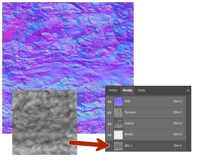
All three colors should be 256 x 256 (512 x 512; 1024 x 1024; 2048 x 2048) pixels and must be saved as 32-bit uncompressed TGA.
The first one, the pink file, should be saved as texture1.tga, it will serve as a diffuse texture.
The second file is only used to produce regular maps that can be saved to a name of your choice.
Use the NVidia filter to produce a normal map based on the second file and save it as normal.tga. This should look similar to the third image above.
Create a cube with roughly equal X, Y, and Z dimensions.
Use box.tga in scattered slot. Apply UVW coordinates using “box” mapping, tiling the values of U, V and W 1.Export the mesh and create a config.txt file, make sure that this model can be successfully placed in the game. Back in 3ds Max use normal.tga in the bump slot. Note that no effect on Max will normally be seen. Make sure your material editor settings match in this image, including box.m.tbumptex as the material name:
In the Normal map, it is possible to display the details that you generate using the texture and insert into the drawing program.
Now proceed in the drawing program 3ds max “0” to the key (or you can go to Render -> Render to Texture …” bring up the render to texture dialog.
In the “Projection Mapping” section we want to check “Enable” you can add the projection modifier here too, but I do it by hand because it allows me to select from a list of objects rather than selecting each one manually in the viewport.
In the “Mapping Coordinates” section, make sure the “:” object is set to “Use Existing Channel” If you have a lot of overlapping UV’s or sloppy UV layout, you will run into problems. Auto-expanding is very inefficient.
Under the “Output” boot we want to click the button “Add… (Add …)” and add “normal Map” with the map selected, you can adjust its settings in the “selected elements Common Settings” Make sure to change where the file will be saved (select … button next to the file name) So you don’t have to lose the map after baking. Also, uncheck the “compress” setting by clicking the Setup button when selecting the output file, otherwise the file will not be loaded into Trainz. You can also resize the map here. Generally speaking for more complex objects you will run into problems if you try and do anything above 2048×2048. Also further under the “Baked Material” boot I checked the “Render to Files Only” Option
Go back up under “Projection Mapping” and click “Options…” You should get the following diagram. Since we are not in the feature using a cage, make sure that “use Cage” is checked. The offset determines how far from the surface the ray will search for more polygons. Edit.
Trainz uses the green channel (vs. max) to make sure “Green:” is set to “up” instead of “down”
Notice in the section “Resolve Hit” is “Ray Miss Color:” In the map that is rendered, it will melt in the red area that was not hit by the surface. It is not important to make sure all pixels hit the surface, in some areas you may not see pixels or notifications. Use your best judgment.
When providing a more complex geometry, sometimes bad normals are raised. A good way to avoid this is to assign material IDs to different parts of your low-poly and their corresponding parts in the highpoly and select “Hit Only Matching Material ID”
Normal map: a texture file used with a diffuse map will allow per-pixel light control. An overview of normal mapping can be found in the article above
The color channels (red, green, blue) on the normal map determine the X, Y and Z value for the pixel of the normal tangent space. This information is not considered human editable, and you should not attempt to manipulate these channels directly. Specifically, do not adjust the dimensions or contrast of an existing normal map. If you need to resize the normal map, you will need to restore the normal map using the original tools. If you need to adjust the bump height in the normal map, you will need to adjust the source geometry and re-map the normal map using the original tools.
Editing a normal map in Photoshop or similar will cause undefined behavior in the game. In addition, any form of lossy compression (for example, JPG format.) will destroy a significant amount of information contained in a normal map. Do not use lossy formats for saving normal maps even as an intermediate step, i.e. (JPG, GIF).
The alpha channel of a normal map is usually used to control specular light per-pixel. White gives a strong mirror, suitable for metals and water. Black does not provide a mirror, more suitable for a dark country. Grays are medium strength mirrors. It is safe to edit the alpha channel with a tool like Photoshop, provided the color channels are not edited in any way.
If no alpha channel is specified, the default normal map will be white with a full alpha channel. Since a white alpha channel indicates a strong specular, which will look strongly metallic or plastic on most textures, it is not usually appropriate to make normal maps without an alpha channel. For this reason, it is recommended that. TGA format is used for alpha channels.
A convenient way to display a normal map in 3D Studio Max is to use the “Normal” Bump map in the bump slot of the material. If you insert a map directly into this slot it will display/render, but the map display as a bump map and will not display correctly. To view Trainz normal maps from maximum during we have to turn the channel green color to display the map correctly. This can be done within the materials editor without actually changing the map.
In the Normal Bump properties under Channel Direction you need to check, “Flip Green (Y)”. Finally, put your usual maps on the “Normal:” Slot.